- 您现在的位置:买卖IC网 > Sheet目录321 > DM240002 (Microchip Technology)BOARD DEV EXPLORER 16 44-PIN
�� �
�
�44-Pin� Demo� Board� User’s� Guide�
�3.2.4.1�
�ADCON1�
�The� ADCON1� register� sets� the� justification� of� the� 10-bit� result� in� the� 16-bit� result� read�
�through� registers� ADRESL� and� ADRESH.� Setting� the� result� to� Left� Justified� means� the�
�8� Most� Significant� bits� and� read� from� ADRESH� and� the� 2� Least� Significant� bits� are� read�
�from� bits� 7� and� 6� of� ADRESL.� ADCON1� also� sets� the� voltage� reference� sources� V� REF+�
�and� V� REF-.� V� REF-� is� the� voltage� at� which� the� result� will� be� zero.� V� REF+� is� the� voltage� at�
�which� the� result� will� be� maximum� (1023).� We� select� the� PIC16F887� V� SS� and� V� DD�
�voltages� respectively.�
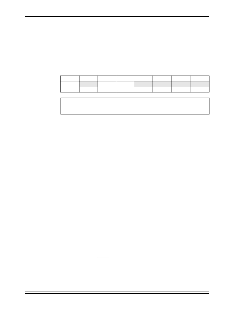
�REGISTER� 3-1:�
�ADCON1:� A/D� CONTROL� REGISTER� 1�
�R/W-0�
�ADFM�
�U-0�
�—�
�R/W-0�
�VCFG1�
�R/W-0�
�VCFG0�
�U-0�
�—�
�U-0�
�—�
�U-0�
�—�
�U-0�
�—�
�bit� 7�
�Legend:�
�bit� 0�
�R� =� Readable� bit�
�W� =� Writable� bit�
�U� =� Unimplemented� bit,� read� as� ‘0’�
�-� n� =� Value� at� POR�
�‘1’� =� Bit� is� set�
�‘0’� =� Bit� is� cleared�
�x� =� Bit� is� unknown�
�bit� 7�
�bit� 6�
�bit� 5�
�bit� 4�
�bit� 3-0�
�3.2.4.2�
�ADFM:� A/D� Conversion� Result� Format� Selection� bit�
�1� =� Right� justified�
�0� =� Left� justified�
�Unimplemented:� Read� as� ‘� 0� ’�
�VCFG1:� Voltage� Reference� bit�
�1� =� V� REF� -� pin�
�0� =� Vss�
�VCFG0:� Voltage� Reference� bit�
�1� =� V� REF� +� pin�
�0� =� V� DD�
�Unimplemented:� Read� as� ‘� 0� ’�
�ADCON0�
�ADCON0� controls� the� ADC� operation.� Bit� 0� turns� on� the� ADC� module� and� bit� 1� starts� a�
�conversion.� Bits� <7:6>� select� the� ratio� between� the� processor� clock� and� conversion�
�speed� and� bits� <5:2>� select� which� channel� the� ADC� will� operate� on.� The� ratio� between�
�the� processor� clock� and� conversion� speed� is� important� because� the� ADC� needs� at�
�least� 1.6� μ� s� per� bit.� Accuracy� degrades� if� the� clock� speed� is� too� high.� As� the� processor�
�clock� speed� increases,� an� increasingly� large� divider� is� necessary� to� keep� the� conver-�
�sion� bit� speed� above� 1.6� μ� s.� Four� MHz� gives� the� fastest� conversion� rate� above� the� min-�
�imum� at� 8:1� ratio.� This� results� in� a� conversion� speed� of� 2� μ� s� per� bit.� Refer� to� the� “T� AD�
�vs.� Device� Operating� Frequencies”� Table� in� the� Analog-to-Digital� section� of� the�
�PIC16F882/883/884/886/887� Data� Sheet� (DS41291)� for� recommended� configurations.�
�For� purposes� of� this� lesson,� the� ADC� must� be� turned� on� and� pointed� to� channel� AN0�
�on� pin� RA0.�
�The� ADC� needs� about� 5� μ� s,� after� changing� channels,� to� allow� the� ADC� sampling� capac-�
�itor� to� settle.� Finally,� we� can� start� the� conversion� by� setting� the� GO� bit� in� ADCON0.� The�
�bit� also� serves� as� the� DONE� flag.� That� is,� the� ADC� will� clear� the� same� bit� when� the� con-�
�version� is� complete.� The� answer� is� then� available� in� ADRESH:ADRESL.� This� lesson�
�takes� the� high� order� 8� bits� of� the� result� and� copies� them� to� the� display� LEDs� attached�
�to� PORTD.�
�DS41296B-page� 20�
�?� 2007� Microchip� Technology� Inc.�
�发布紧急采购,3分钟左右您将得到回复。
相关PDF资料
DM240011
KIT STARTER MPLAB FOR PIC24F MCU
DM240021
KIT STARTER MPLAB FOR PIC24H
DM240311
BOARD DEV PIC24F16KA102 XLP
DM300018
BOARD DEMO DSPICDEM 2
DM300019
BOARD DEMO DSPICDEM 80L STARTER
DM300024
KIT DEMO DSPICDEM 1.1
DM330012
KIT USB STARTER FOR DSPIC33E
DM330013
MICROSTICK DSPIC33F/PIC24H BOARD
相关代理商/技术参数
DM240002
制造商:Microchip Technology Inc 功能描述:Explorer 16 kit(44-PIN) w/ PIC24FJ64GA00
DM240011
功能描述:开发板和工具包 - PIC / DSPIC MPLAB Starter Kit for PIC24F MCU RoHS:否 制造商:Microchip Technology 产品:Starter Kits 工具用于评估:chipKIT 核心:Uno32 接口类型: 工作电源电压:
DM240012
功能描述:开发板和工具包 - PIC / DSPIC PIC24E USB Starter Kit RoHS:否 制造商:Microchip Technology 产品:Starter Kits 工具用于评估:chipKIT 核心:Uno32 接口类型: 工作电源电压:
DM240013-1
功能描述:开发板和工具包 - PIC / DSPIC Microstick for 3V PIC24F K-series
RoHS:否 制造商:Microchip Technology 产品:Starter Kits 工具用于评估:chipKIT 核心:Uno32 接口类型: 工作电源电压:
DM240013-2
功能描述:开发板和工具包 - PIC / DSPIC
RoHS:否 制造商:Microchip Technology 产品:Starter Kits 工具用于评估:chipKIT 核心:Uno32 接口类型: 工作电源电压:
DM240014
制造商:Microchip Technology Inc 功能描述:MICROSTICK FOR USB PIC24F - Boxed Product (Development Kits) 制造商:Microchip Technology Inc 功能描述:ACCY MICROSTICK USB PIC24F 制造商:Microchip Technology Inc 功能描述:MICROSTICK USB PIC24F
DM240015
制造商:Microchip Technology Inc 功能描述:MPLAB STARTER KIT FOR PIC24F INTELLIGENT INTEGRATED ANALOG - Boxed Product (Development Kits) 制造商:Microchip Technology Inc 功能描述:KIT MPLAB STARTER FOR PIC24F ANL 制造商:Microchip Technology Inc 功能描述:PIC24F GC INTELLIGENT ANALOG DEV KIT 制造商:Microchip Technology Inc 功能描述:PIC24F, GC INTELLIGENT ANALOG, DEV KIT 制造商:Microchip Technology Inc 功能描述:Starter Kit for PIC24F Intelligent Integrated Analog Series 制造商:Microchip Technology Inc 功能描述:Development Boards & Kits - PIC / DSPIC 制造商:Microchip Technology Inc 功能描述:PIC24F, GC INTELLIGENT ANALOG, DEV KIT, Silicon Manufacturer:Microchip, Core Arc 制造商:Microchip Technology Inc 功能描述:PIC24F, GC INTELLIGENT ANALOG, DEV KIT, Silicon Manufacturer:Microchip, Core Architecture:PIC, Core Sub-Architecture:PIC24, Silicon Core Number:PIC24FJ128GC010, Silicon Family Name:PIC24FJxxxGCxxx, Kit Contents:Starter Board 制造商:Microchip Technology Inc 功能描述:MPLAB Starter Kit for PIC24F Intelligent Integrated Analog, Starter Kits
DM240021
功能描述:开发板和工具包 - PIC / DSPIC MPLAB STARTER KIT FOR PIC24H RoHS:否 制造商:Microchip Technology 产品:Starter Kits 工具用于评估:chipKIT 核心:Uno32 接口类型: 工作电源电压: